Breaking Down First Day at Maze Corp’s Graphics
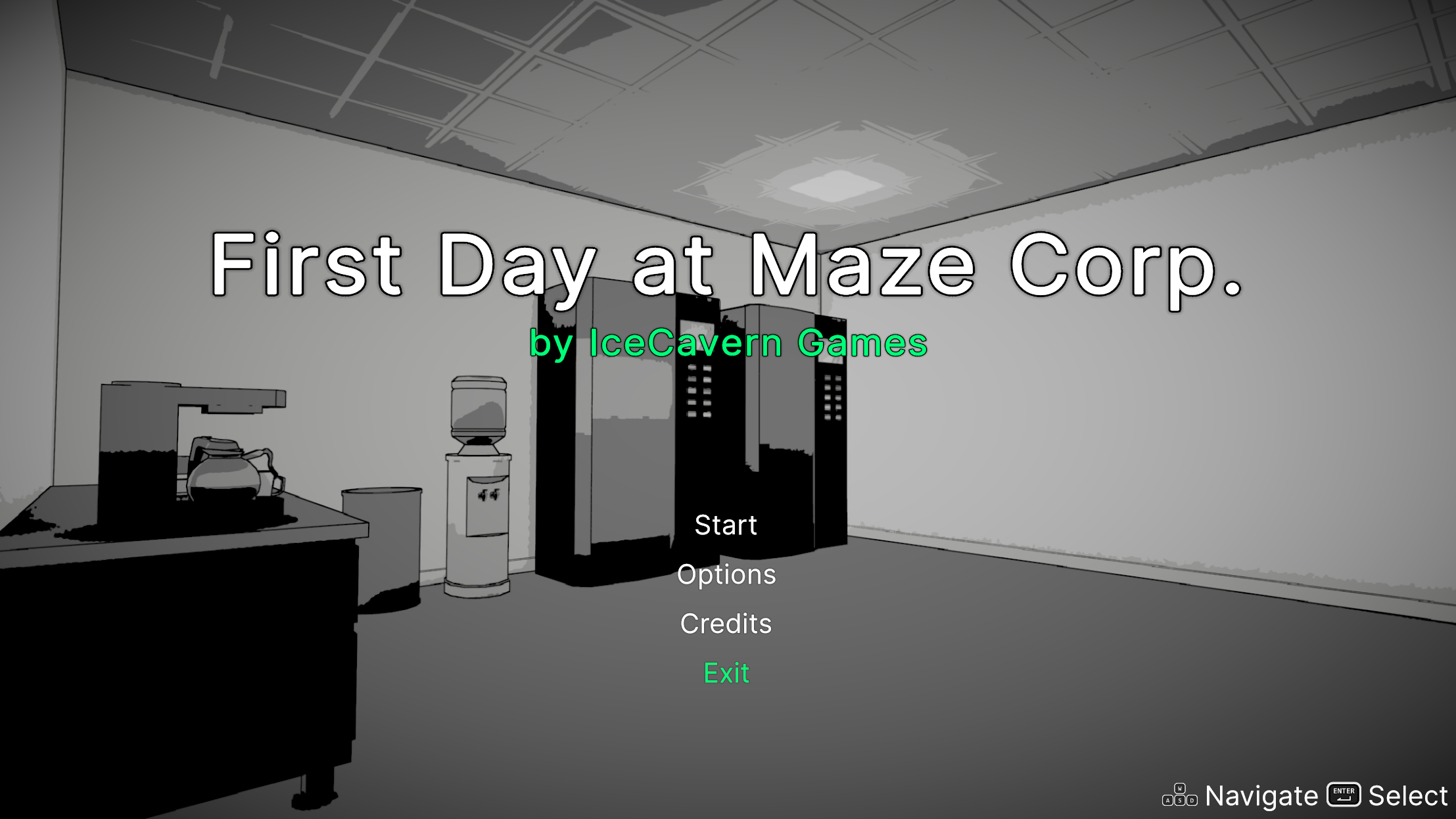
I recently participated in Brackeys Game Jam 2025.1 in which we were given a week to make a game fitting the theme “nothing can go wrong”. We came up with First Day at Maze Corp. a game in which you must navigate a maze of an office on your first day. I was lucky enough to be working on this with my friend @Colby who could handle most of the gameplay code and give me some time to focus on the aesthetics. I’m really satisfied with how the game ended up looking (especially for only a week of dev time) and wanted to break down the techniques I used to achieve our look.
This is not going to be a comprehensive end-to-end tutorial. I provide code snippets to help explain ideas but it’s not a full on implementation tutorial. If you’re interested, the source for the game is publicly available on github.
Overview
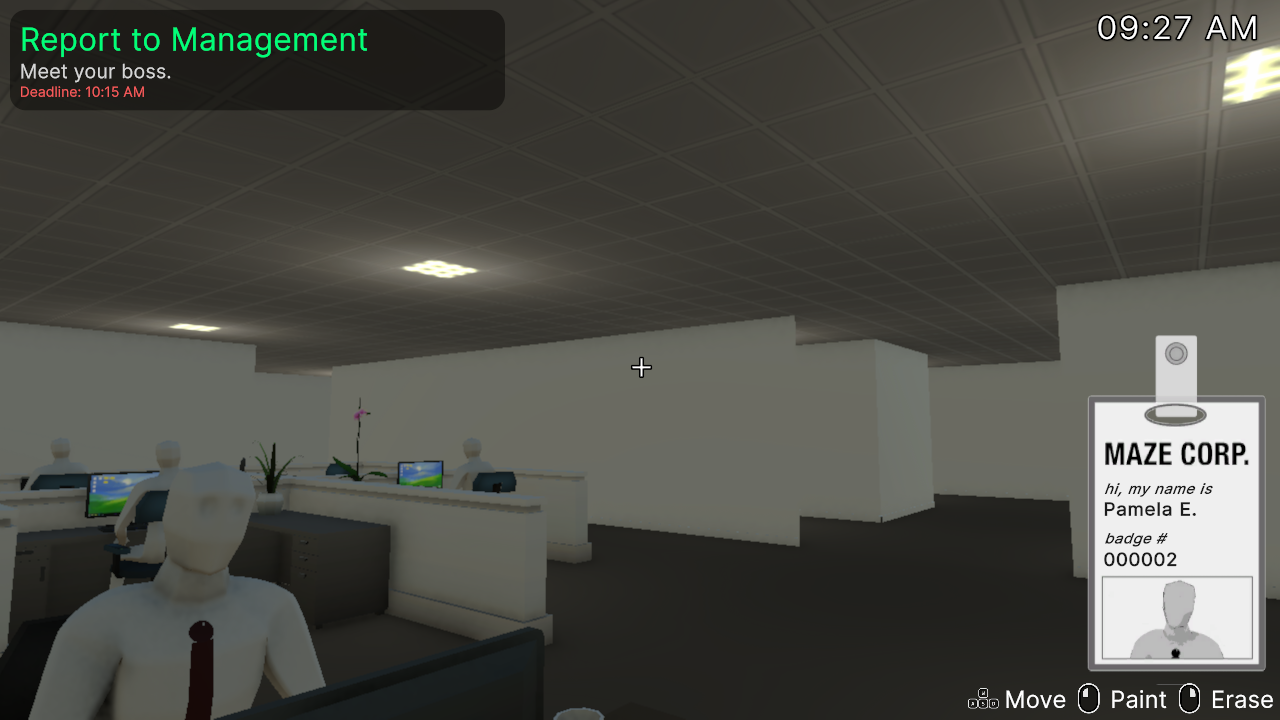
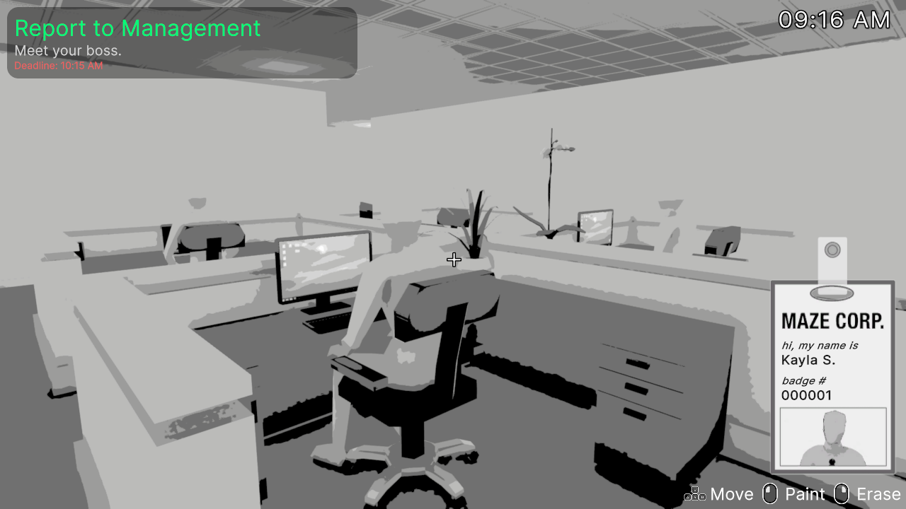
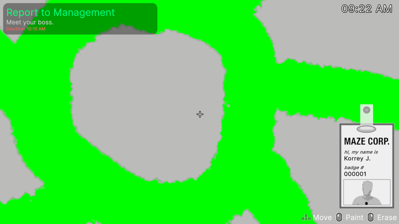
If we study the above screenshot from the game a few things standout.
- Most of the image is grayscale and posterized (colors are limited, hard edges between different colors)
- Hard black lines are drawn on the edges of objects
- The only color comes from drawings on the walls
Post-Processing
Most of the game’s final appearance is driven by a custom post-processing render pass. Post-processing is the act of applying effects to an already rendered image. Unity URP comes with several built in post-processing effects you might be familiar with such as bloom, depth of field, color correction, and more. With Unity’s Scriptable Render Pipeline it’s possible to inject your own effect into the rendering pipeline.
Custom Renderer Feature
In Unity 6 you can create a Custom Renderer Feature by right clicking in your assets folder and selecting Create > Rendering > URP Renderer Feature. This creates a new C# script with the following template code.
public class CustomRenderPassFeature : ScriptableRendererFeature
{
    class CustomRenderPass : ScriptableRenderPass
    {
        // This class stores the data needed by the RenderGraph pass.
        // It is passed as a parameter to the delegate function that executes the RenderGraph pass.
        private class PassData
        {
        }

        // This static method is passed as the RenderFunc delegate to the RenderGraph render pass.
        // It is used to execute draw commands.
        static void ExecutePass(PassData data, RasterGraphContext context)
        {
        }

        // RecordRenderGraph is where the RenderGraph handle can be accessed, through which render passes can be added to the graph.
        // FrameData is a context container through which URP resources can be accessed and managed.
        public override void RecordRenderGraph(RenderGraph renderGraph, ContextContainer frameData)
        {
            const string passName = "Render Custom Pass";

            // This adds a raster render pass to the graph, specifying the name and the data type that will be passed to the ExecutePass function.
            using (var builder = renderGraph.AddRasterRenderPass<PassData>(passName, out var passData))
            {
                // Use this scope to set the required inputs and outputs of the pass and to
                // setup the passData with the required properties needed at pass execution time.

                // Make use of frameData to access resources and camera data through the dedicated containers.
                // Eg:
                // UniversalCameraData cameraData = frameData.Get<UniversalCameraData>();
                UniversalResourceData resourceData = frameData.Get<UniversalResourceData>();

                // Setup pass inputs and outputs through the builder interface.
                // Eg:
                // builder.UseTexture(sourceTexture);
                // TextureHandle destination = UniversalRenderer.CreateRenderGraphTexture(renderGraph, cameraData.cameraTargetDescriptor, "Destination Texture", false);

                // This sets the render target of the pass to the active color texture. Change it to your own render target as needed.
                builder.SetRenderAttachment(resourceData.activeColorTexture, 0);

                // Assigns the ExecutePass function to the render pass delegate. This will be called by the render graph when executing the pass.
                builder.SetRenderFunc((PassData data, RasterGraphContext context) => ExecutePass(data, context));
            }
        }

        // NOTE: This method is part of the compatibility rendering path, please use the Render Graph API above instead.
        // This method is called before executing the render pass.
        // It can be used to configure render targets and their clear state. Also to create temporary render target textures.
        // When empty this render pass will render to the active camera render target.
        // You should never call CommandBuffer.SetRenderTarget. Instead call <c>ConfigureTarget</c> and <c>ConfigureClear</c>.
        // The render pipeline will ensure target setup and clearing happens in a performant manner.
        public override void OnCameraSetup(CommandBuffer cmd, ref RenderingData renderingData)
        {
        }

        // NOTE: This method is part of the compatibility rendering path, please use the Render Graph API above instead.
        // Here you can implement the rendering logic.
        // Use <c>ScriptableRenderContext</c> to issue drawing commands or execute command buffers
        // https://docs.unity3d.com/ScriptReference/Rendering.ScriptableRenderContext.html
        // You don't have to call ScriptableRenderContext.submit, the render pipeline will call it at specific points in the pipeline.
        public override void Execute(ScriptableRenderContext context, ref RenderingData renderingData)
        {
        }

        // NOTE: This method is part of the compatibility rendering path, please use the Render Graph API above instead.
        // Cleanup any allocated resources that were created during the execution of this render pass.
        public override void OnCameraCleanup(CommandBuffer cmd)
        {
        }
    }

    CustomRenderPass m_ScriptablePass;

    /// <inheritdoc/>
    public override void Create()
    {
        m_ScriptablePass = new CustomRenderPass();

        // Configures where the render pass should be injected.
        m_ScriptablePass.renderPassEvent = RenderPassEvent.AfterRenderingOpaques;
    }

    // Here you can inject one or multiple render passes in the renderer.
    // This method is called when setting up the renderer once per-camera.
    public override void AddRenderPasses(ScriptableRenderer renderer, ref RenderingData renderingData)
    {
        renderer.EnqueuePass(m_ScriptablePass);
    }
}
This template is pretty heavily commented which helps us figure out how to use it. The most important methods are RecordRenderGraph and ExecutePass, while PassData is used to store any data that needs to be passed from RecordRenderGraph to ExecutePass.
RecordRenderGraph
Before we look at how I filled in these methods, let’s establish what we’re actually trying to do. Since this is a post-processing effect we want our effect to have access to the camera rendered image, then have our effect make some changes to the camera image and finally display it back to the screen. The actual effect code will take place in a shader with our CustomRendererFeature controlling the inputs to that shader.
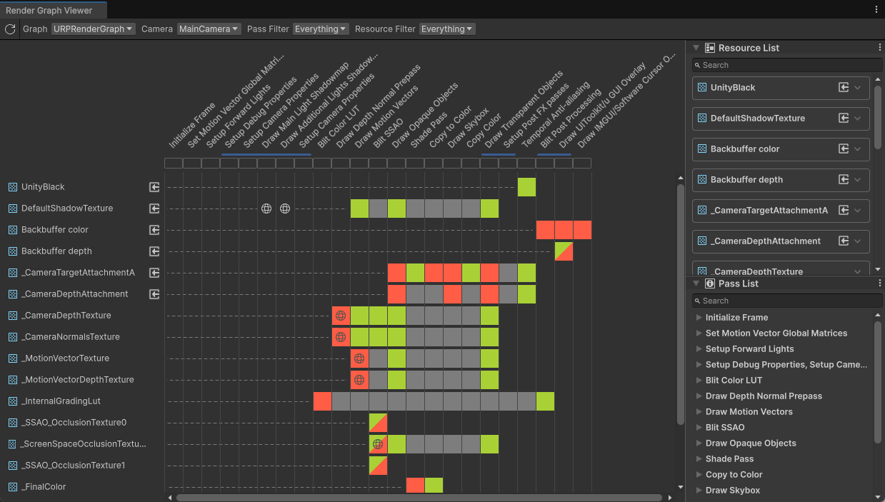
How do we insert our own code into the rendering pipeline? Render Graph is a new Unity API for doing just that. Unity builds out a render graph for URP and HDRP render pipelines, however, using a ScriptableRendererFeature and ScriptableRenderPass you are free to insert your own steps into these pipelines. You can view your project’s render graph in the Render Graph Viewer window located at Window > Analysis > Render Graph Viewer
The ScriptableRendererFeature class is responsible for adding render passes to the renderer and the ScriptableRenderPass takes care of describing the render graph and actually executing the shader.
Now we can finally look at the code for RecordRenderGraph
public override void RecordRenderGraph(RenderGraph renderGraph, ContextContainer frameData)
{
    const string passName = "ShadePass";

    // Make use of frameData to access resources and camera data through the dedicated containers.
    UniversalResourceData resourceData = frameData.Get<UniversalResourceData>();
    TextureHandle dst =
        UniversalRenderer.CreateRenderGraphTexture(renderGraph, _rtDescriptor, "_FinalColor", false);
    TextureHandle cameraColor = resourceData.activeColorTexture;

    // This adds a raster render pass to the graph, specifying the name and the data type that will be passed to the ExecutePass function.
    using (var builder = renderGraph.AddRasterRenderPass<PassData>(passName, out var passData))
    {
        // Use this scope to set the required inputs and outputs of the pass and to
        // setup the passData with the required properties needed at pass execution time.
        passData._cameraColor = cameraColor;
        builder.UseTexture(passData._cameraColor);

        // Set render target to dst texture
        builder.SetRenderAttachment(dst, 0);

        // Assigns the ExecutePass function to the render pass delegate. This will be called by the render graph when executing the pass.
        builder.SetRenderFunc((PassData data, RasterGraphContext context) => ExecutePass(data, context));
    }

    RenderGraphUtils.BlitMaterialParameters blitParams = new(dst, cameraColor, _material, 1);
    renderGraph.AddBlitPass(blitParams, "Copy to Color");
}
There is a lot going on here, so let’s start from the top.
passNamesimply names the pass, this name will show up in the render graph view windowdstis aTextureHandleto a new image that we will be writing to in our shadercameraColoris an existingTextureHandlethat references the camera’s color texture- Next we give passData a reference to
cameraColor(more on this later) and tell the render graph builder that we’re using that texture builder.SetRenderAttachment(dst, 0);sets the render target (the image we draw to) for the shader pass 0builder.SetRenderFuncassignsExecutePassas the function that is called when the pass is executed- Finally we add a Blit pass to copy the texture we write to (dst) back to the camera color texture. This is required because in our shader we need to read the camera color texture, however, we can’t read and write to the same texture in the same pass
PassData
The only data I need to send to ExecutePass is the camera color texture.
// This class stores the data needed by the RenderGraph pass.
// It is passed as a parameter to the delegate function that executes the RenderGraph pass.
private class PassData
{
    internal TextureHandle _cameraColor;
}
ExecutePass
In ExecutePass we need to set variables as well as copy (Blit) the camera color texture to our shader. At the top of CustomShadingRenderPass I get the Ids for all the shader variables I need.
private static readonly int _colorId = Shader.PropertyToID("_Color");
private static readonly int _whiteCutoffId = Shader.PropertyToID("_WhiteCutoff");
private static readonly int _NormalThresholdId = Shader.PropertyToID("_NormalThreshold");
private static readonly int _DepthThresholdId = Shader.PropertyToID("_DepthThreshold");
private static readonly int _DepthDistanceModulationId = Shader.PropertyToID("_DepthDistanceModulation");
private static readonly int _DepthModulationPowerId = Shader.PropertyToID("_DepthModulationPower");
And then in ExecutePass…
// This method is passed as the RenderFunc delegate to the RenderGraph render pass.
// It is used to execute draw commands.
private void ExecutePass(PassData data, RasterGraphContext context)
{
    if (_material == null)
        return;

    _material.SetColor(_colorId, _settings.color);
    _material.SetFloat(_whiteCutoffId, _settings.WhiteCutoff);
    _material.SetFloat(_NormalThresholdId, _settings.NormalThreshold);
    _material.SetFloat(_DepthThresholdId, _settings.DepthThreshold);
    _material.SetFloat(_DepthDistanceModulationId, _settings.DepthDistanceModulation);
    _material.SetFloat(_DepthModulationPowerId, _settings.DepthModulationPower);

    Blitter.BlitTexture(context.cmd, data._cameraColor, new Vector4(1, 1, 0, 0), _material, 0);
}
This method is fairly straightforward. We just set variables on our shader to their corresponding settings in our renderer settings and then call Blitter.BlitTexture to copy the camera color texture passed in through PassData using the command buffer provided in context.
The Shader
All of the Custom Renderer Feature code was setup in order to be able to run our shader code. Edge detection is by far the most complicated part of the shader code, so I’ll leave that for last. A simplified version of my shader with only posterization looks something like this
Shader "Hidden/ShadingPostProcess"
{
    HLSLINCLUDE

    #include "Packages/com.unity.render-pipelines.universal/ShaderLibrary/Core.hlsl"
    #include "Packages/com.unity.render-pipelines.core/Runtime/Utilities/Blit.hlsl"

    ENDHLSL

    SubShader
    {
        Tags
        {
            "RenderType"="Opaque"
            "RenderPipeline"="UniversalPipeline"
        }
        LOD 100
        ZWrite Off Cull Off

        Pass
        {
            Name "ShadePass"

            HLSLPROGRAM

            #pragma vertex Vert
            #pragma fragment Frag

            float4 _Color;

            float4 Frag(Varyings input) : SV_TARGET
            {
                // Posterization
                float4 camColor = SAMPLE_TEXTURE2D(_BlitTexture, sampler_LinearClamp, input.texcoord);
                float luma = dot(camColor.rgb, float3(0.2126729, 0.7151522, 0.0721750));
                luma = sqrt(luma) * 10;
                luma = floor(luma);
                luma /= 6;

                return float4(luma.xxx * _Color, 1);
            }

            ENDHLSL
        }

        Pass
        {
            Name "Copy to Color"

            HLSLPROGRAM

            #pragma vertex Vert
            #pragma fragment Frag

            float4 Frag(Varyings input) : SV_TARGET
            {
                return SAMPLE_TEXTURE2D(_BlitTexture, sampler_LinearClamp, input.texcoord);
            }

            ENDHLSL
        }
    }
}
If you’ve never written a shader or have only used shader graph, there’s a lot going on here that’s probably confusing. I don’t want to cover shader basics in this post as I’m trying to keep it more about the process and less of an end to end tutorial. If you’re interested in learning about how to write shaders for URP, Cyanilux has a great tutorial here.
Since we’re blitting the camera texture to our shader, we want to #include "Packages/com.unity.render-pipelines.core/Runtime/Utilities/Blit.hlsl". This file has a vertex function and associated Varyings struct defined for us. We can then define our own Fragment function that first samples the _BlitTexture defined in the Blit hlsl function to get the camera color.
float luma = dot(camColor.rgb, float3(0.2126729, 0.7151522, 0.0721750));
This line converts the rgb color from the camera color texture to a luminescence value by taking the dot product of the camera’s rgb values against a common vector used for this purpose. We can look at the result of this operation by returning from the fragment function early like so.
return float4(luma.xxx, 1);
You may notice that there is already some color banding in the image. This is due to how I baked the lightmaps for the office. I wanted to decrease the final size of the game as much as possible so the light maps for this scene are baked at a fairly low resolution which results in the banding you can see around the desk. I actually didn’t notice this was going on until I wrote this post because I assumed this look was coming entirely from the next few lines where I do something similar in the shader.
luma *= 10;
luma = floor(luma);
luma /= 10;
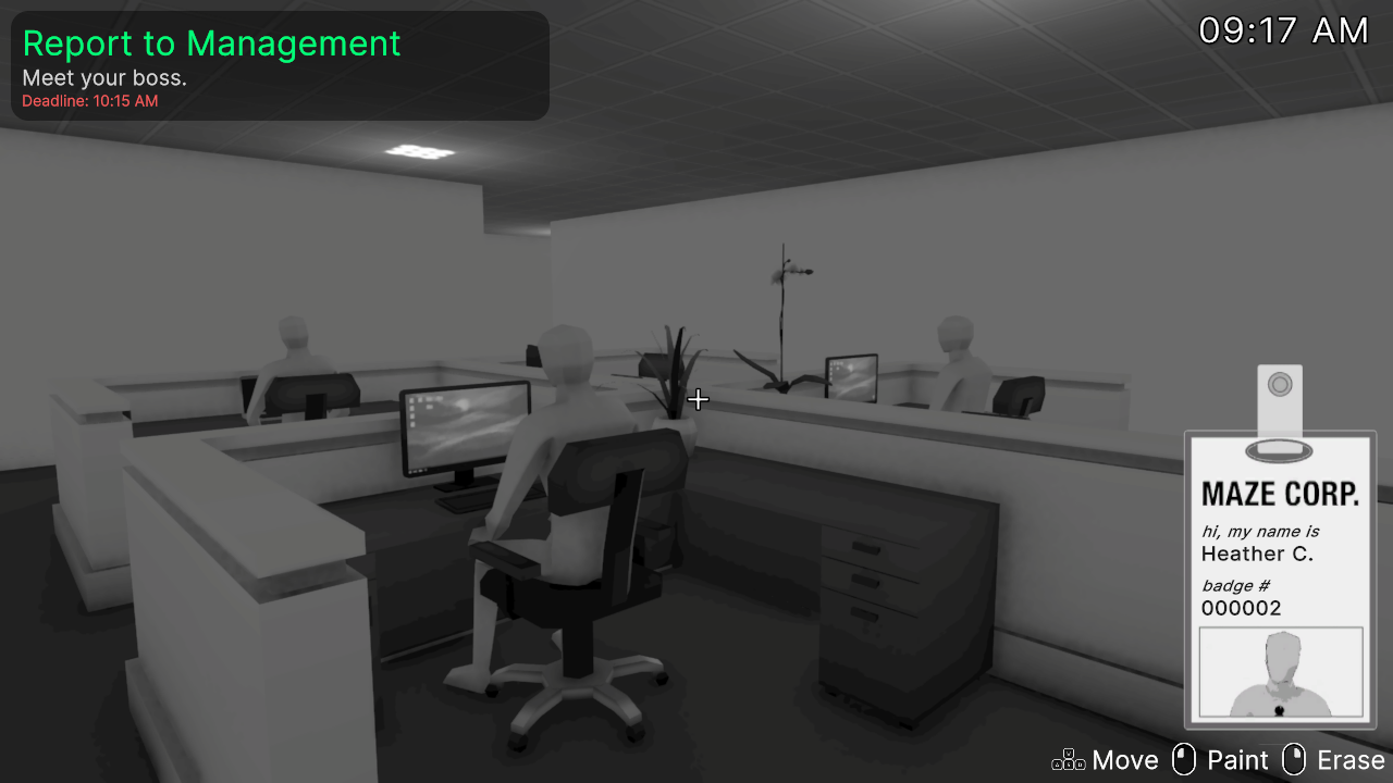
These lines of code do a couple things. First I multiply the luma value by 10, transforming the value from a range of 0-1 to a range of 0-10. By flooring this new value we end up with integer only values in the range of 0-9, and then if we were to divide by 10 we end up with values of 0, 0.1, 0.2, .... Doing this creates distinct grayscale color bands and looks like this and is often called posterization.
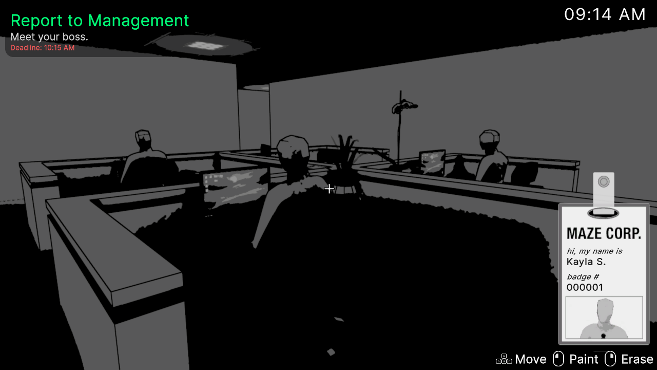
But hang on, this is way too dark! If you looked closely at the shader code at the beginning of this section you might have noticed that it doesn’t match this last code snippet. I actually settled on these lines for the posterization.
luma = sqrt(luma) * 10;
luma = floor(luma);
luma /= 6;
I use the square root of luma * 10 instead of just luma and divide it by 6 instead of 10 at the end. This creates a color range that tends towards being a little more white and results in the look we settled on in the final game.
In the future I’d love to spend more time on refining the look here but it was a game jam and I had to move on!
Copy to Color Pass
You may have noticed a second pass in the shader code.
Pass
{
    Name "Copy to Color"

    HLSLPROGRAM

    #pragma vertex Vert
    #pragma fragment Frag

    float4 Frag(Varyings input) : SV_TARGET
    {
        return SAMPLE_TEXTURE2D(_BlitTexture, sampler_LinearClamp, input.texcoord);
    }

    ENDHLSL
}
This is a simple pass that also takes advantage of the vertex function in Blit.hlsl. Like I mentioned before, we need a separate blit pass to copy the result of the texture we wrote to in the first pass to the camera color texture. That’s all this pass does.
Edge Detection
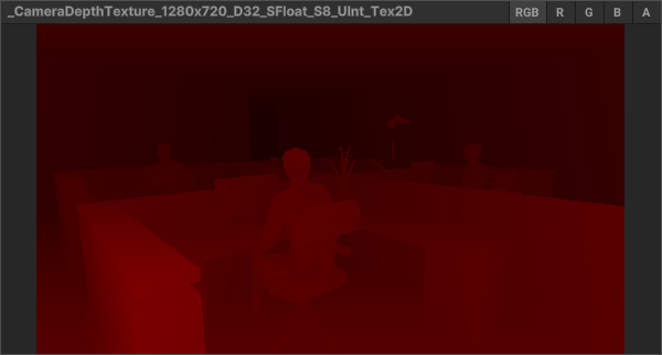
Edge detection is a lot more complicated and drastically increases the number of lines in the shader file. There’s a great tutorial here that covers the details. At a basic level though I look for discontinuities in the image using two different textures generated in the render pipeline.
- The Camera Depth Texture contains information about how far from the camera each pixel in the image is
- The Camera Normals Texture contains information about the normal vector of each pixel of the image
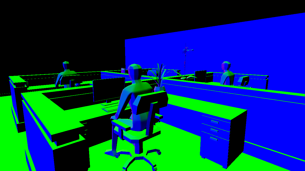
In my post-processing shader I sample pixels around the current pixel and look for any large differences in color using the Roberts Cross algorithm. If there’s a large difference in color around the current pixel we can determine that there must be an edge there.
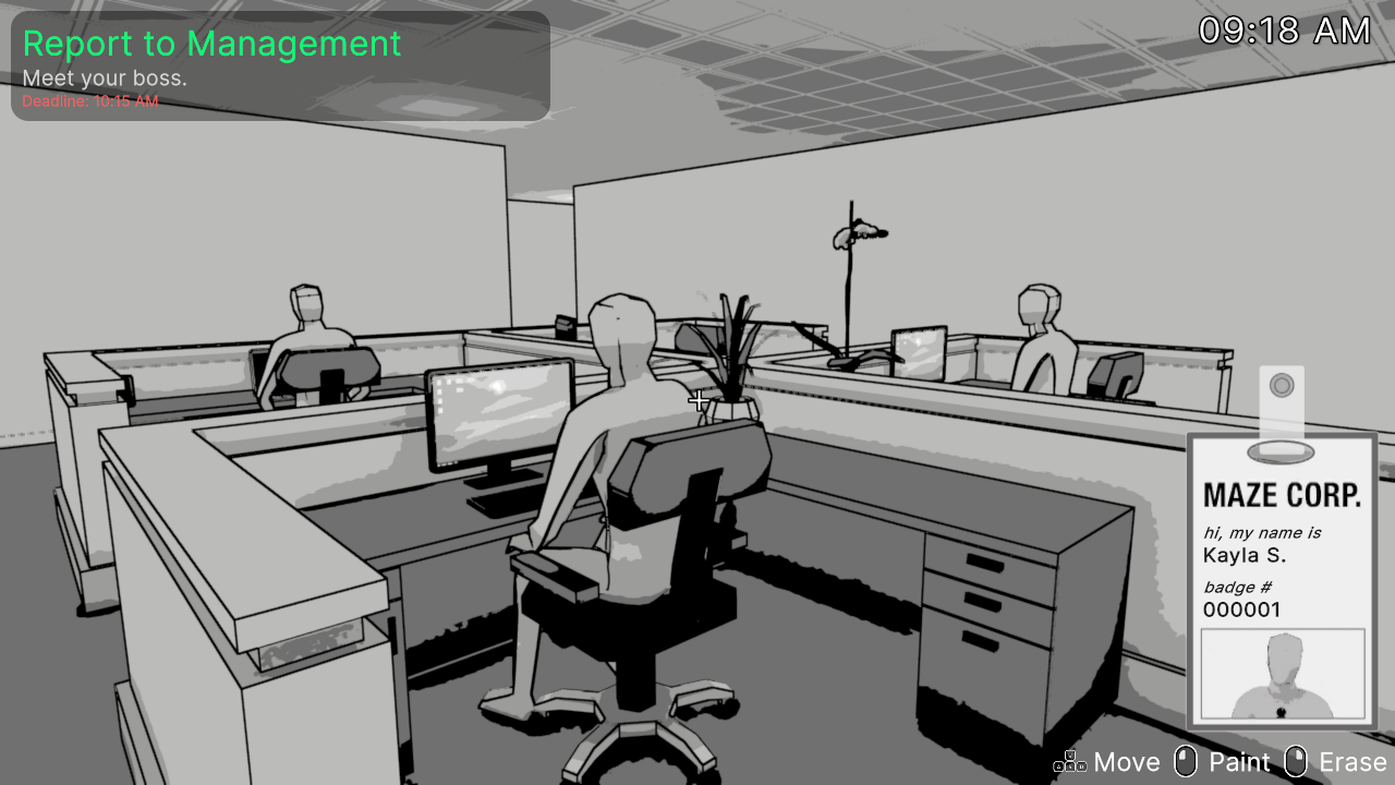
Finally we arrive at the final post-processed image.
The full shader code is available on github
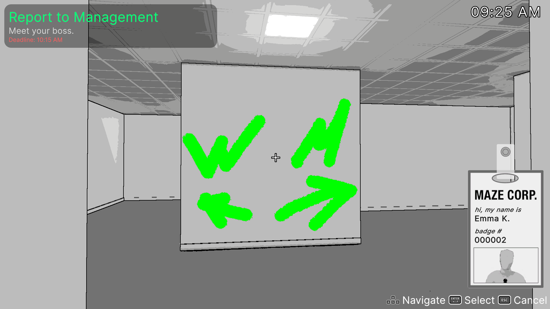
Painting the Walls
All of the walls in First Day at Maze Corp. can be painted on by the player. The way this works is conceptually pretty simple! When a wall is painted on for the first time, a texture is generated to store which areas of the wall have been painted. This texture is then drawn on top of the base wall material.
TexturePaint Shader
The TexturePaint shader handles drawing to a RenderTexture given an input position from the player’s cursor.
Pass
{
    Name "UVRemapPass"

    HLSLPROGRAM

    #include "Packages/com.unity.render-pipelines.universal/ShaderLibrary/Core.hlsl"

    #pragma vertex Vert
    #pragma fragment Frag

    sampler2D _MaskTex;
    float3 _PainterPosition;
    float _Radius;
    float _Hardness;
    float _Strength;
    float4 _PainterColor;
    float _PrepareUV;

    struct Attributes
    {
        float4 vertex : POSITION;
        float2 texcoord : TEXCOORD0;
    };

    struct Varyings
    {
        float4 vertex : SV_POSITION;
        float2 texcoord : TEXCOORD0;
        float4 worldPos : TEXCOORD1;
    };

    float mask(float3 position, float3 center, float radius, float hardness)
    {
        float m = distance(center, position);
        return 1 - smoothstep(radius * hardness, radius, m);
    }

    Varyings Vert(Attributes input)
    {
        Varyings o;

        o.worldPos = mul(unity_ObjectToWorld, input.vertex);
        o.texcoord = input.texcoord;
        float4 uv = float4(0, 0, 0, 1);
        uv.xy = float2(1, _ProjectionParams.x) * (input.texcoord.xy * float2(2, 2) - float2(1, 1));
        o.vertex = uv;

        return o;
    }

    float4 Frag(Varyings input) : SV_TARGET
    {
        if (_PrepareUV > 0)
            return float4(0, 0, 0, 0);

        float4 color = tex2D(_MaskTex, input.texcoord);
        float f = mask(input.worldPos, _PainterPosition, _Radius, _Hardness);
        float edge = f * _Strength;
        return lerp(color, _PainterColor, edge);
    }

    ENDHLSL
}
Let’s break this down
- The Vert function converts the object’s input UVs (what you use for texture mapping) into world space. This is important because we have to associate the spot the player clicks on with a location in the object’s UV space.
- The Frag function handles two different things. If
_PrepareUVis set to 1 we simply just fill the texture with a black, fully transparent color. This is called when the texture is created to initialize the image. Otherwise this function handles actually filling the texture with paint based on_PainterPosition(player’s cursor position) and several other variables to control the look and size of the paint. Themaskfunction generates an edge value between 0 and 1 that I can then use in the finallerpcall to determine the output color of the pixel. For example, an edge value of 0 means nothing is being drawn of this pixel so use the old pixel color. 1 means use the paint color, and somewhere inbetween blends between the two colors (for a soft brush falloff).
This shader is only run when the player is actively painting something. Therefore let’s hop back into C# and see how that’s done.
Paintables
Our player input will perform a raycast from the cursor position to determine what object the cursor is pointing at. If the raycast hit object has a Paintable component attached we know we can paint onto it.
private void Draw(Color color, float radius)
{
    Vector3 position = Input.mousePosition;
    Ray ray = _mainCamera.ScreenPointToRay(position);
    RaycastHit hit;

    if (Physics.Raycast(ray, out hit, 7.0f, ~_ignoreLayers))
    {
        Debug.DrawRay(ray.origin, hit.point - ray.origin, Color.red);
        Paintable paintable = hit.collider.GetComponent<Paintable>();

        if (paintable)
            paintable.Paint(hit.point, radius, _strength, _hardness, color);
    }
}
Everything in the game that is paintable has a Paintable MonoBehaviour component attached to it and has these methods
private void InitializePaintTexture()
{
    _paintTextureManager.CreateTexture(_uniqueObject.Id, out _paintTexture);

    _paintableMaterial.SetFloat(_prepareUVId, 1);
    _commandBuffer = new CommandBuffer();
    _commandBuffer.name = $"Paintable Command Buffer: {gameObject.name}";
    _commandBuffer.SetRenderTarget(_paintTexture.Mask);
    _commandBuffer.DrawRenderer(_renderer, _paintableMaterial, 0);
    _commandBuffer.SetRenderTarget(_paintTexture.Support);
    _commandBuffer.Blit(_paintTexture.Mask, _paintTexture.Support);
    Graphics.ExecuteCommandBuffer(_commandBuffer);
    _commandBuffer.Clear();

    _paintDrawMaterial.SetTexture("_MaskTexture", _paintTexture.Support);
    _hasPaintTexture = true;
}
InitializePaintTexture creates a new paint texture on our PaintTextureManager and returns a reference to it through an out variable. _paintTexture is an instance of a struct that holds two RenderTextures
public struct PaintTexture
{
    public RenderTexture Mask;
    public RenderTexture Support;
}
- Mask is the texture we actually draw on in the shader
- Support is the texture used for Blits because we can’t read and write the same image in a pass
The next lines of InitializePaintTexture do the following:
_paintableMaterial.SetFloat(_prepareUVId, 1);Tells our shader we’re initializing the texture with 0s_commandBuffer = new CommandBuffer();creates a new command buffer for graphics calls_commandBuffer.SetRenderTarget(_paintTexture.Mask);sets the output of our shader to the Mask image_commandBuffer.DrawRenderer(_renderer, _paintableMaterial, 0);executes the shader_commandBuffer.SetRenderTarget(_paintTexture.Support);sets the output of the next call to the Support image_commandBuffer.Blit(_paintTexture.Mask, _paintTexture.Support);blits the mask texture to the Support textureGraphics.ExecuteCommandBuffer(_commandBuffer);executes the command buffer. None of the command buffer calls are run until this is called, then they all are run in the order they were called above.- Finally
_paintDrawMaterial.SetTexture("_MaskTexture", _paintTexture.Support);sets the_MaskTexturevariable of the paintMaterial to the Support texture.
Next is the Paint method
public void Paint(Vector3 position, float radius, float hardness, float strength, Color color)
{
    if (!_hasPaintTexture)
        InitializePaintTexture();

    _paintableMaterial.SetFloat(_prepareUVId, 0);
    _paintableMaterial.SetVector(_positionId, position);
    _paintableMaterial.SetFloat(_radiusId, radius);
    _paintableMaterial.SetFloat(_hardnessId, hardness);
    _paintableMaterial.SetFloat(_strengthId, strength);
    _paintableMaterial.SetColor(_colorId, color);
    _paintableMaterial.SetTexture(_textureId, _paintTexture.Support);

    _commandBuffer.SetRenderTarget(_paintTexture.Mask);
    _commandBuffer.DrawRenderer(_renderer, _paintableMaterial, 0);

    _commandBuffer.SetRenderTarget(_paintTexture.Support);
    _commandBuffer.Blit(_paintTexture.Mask, _paintTexture.Support);

    Graphics.ExecuteCommandBuffer(_commandBuffer);
    _commandBuffer.Clear();
}
This method is similar but sets many more variables to control the look of the paint and sets _prepareUV to 0 of course. This runs the other branch of the Fragment shader as explained above.
The Paint Material
The final piece of the paint effect is the shader for actually drawing the paint. I used shader graph for this one.
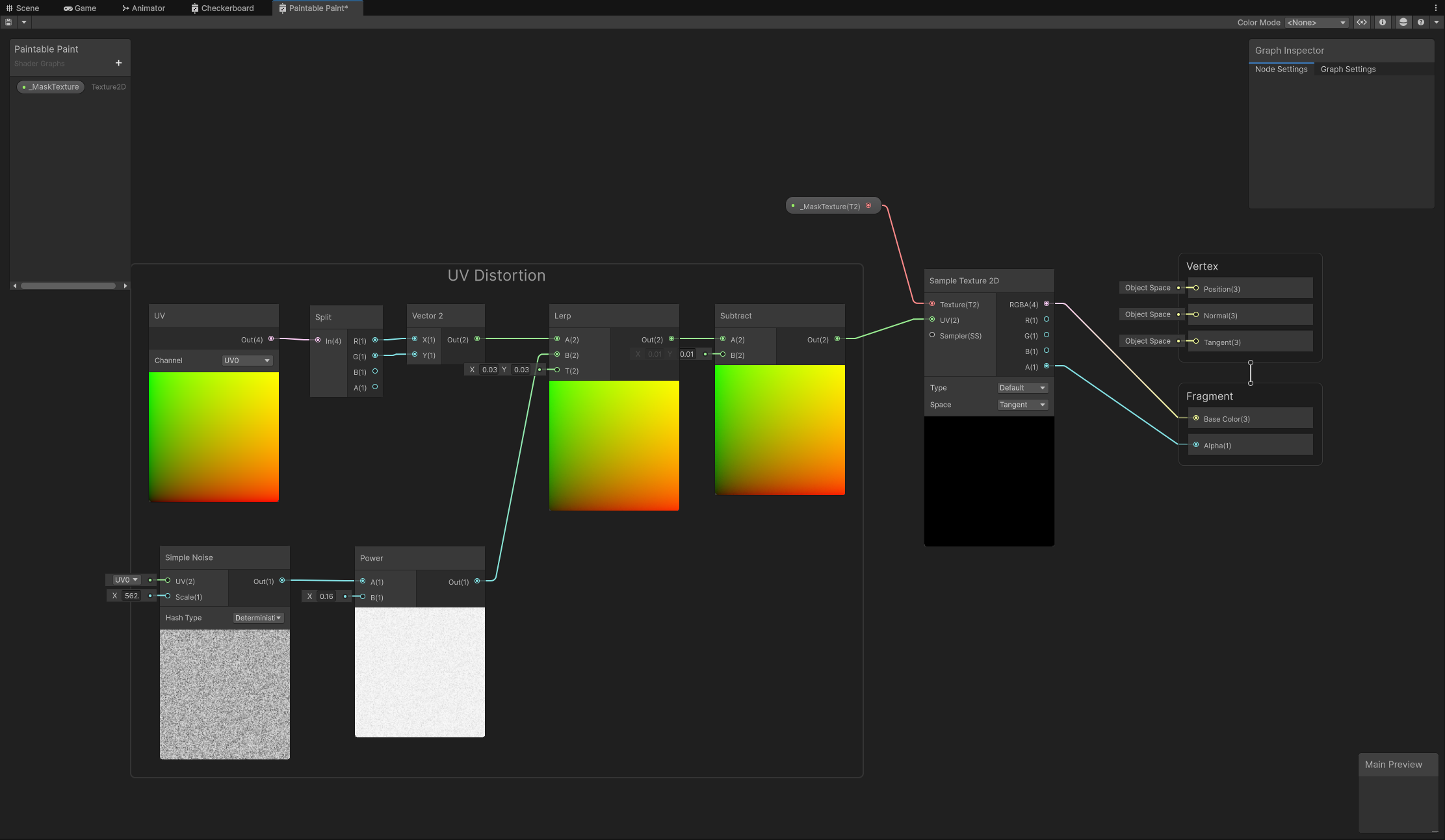
Luckily this one’s pretty simple. The only necessary node is the Sample Texture 2D node. This samples the _MaskTexture variable we set in C#. The other nodes do some minor UV distortion to give the paint more of a, well, paint look. This also helps hide the low resolution of the paint texture.

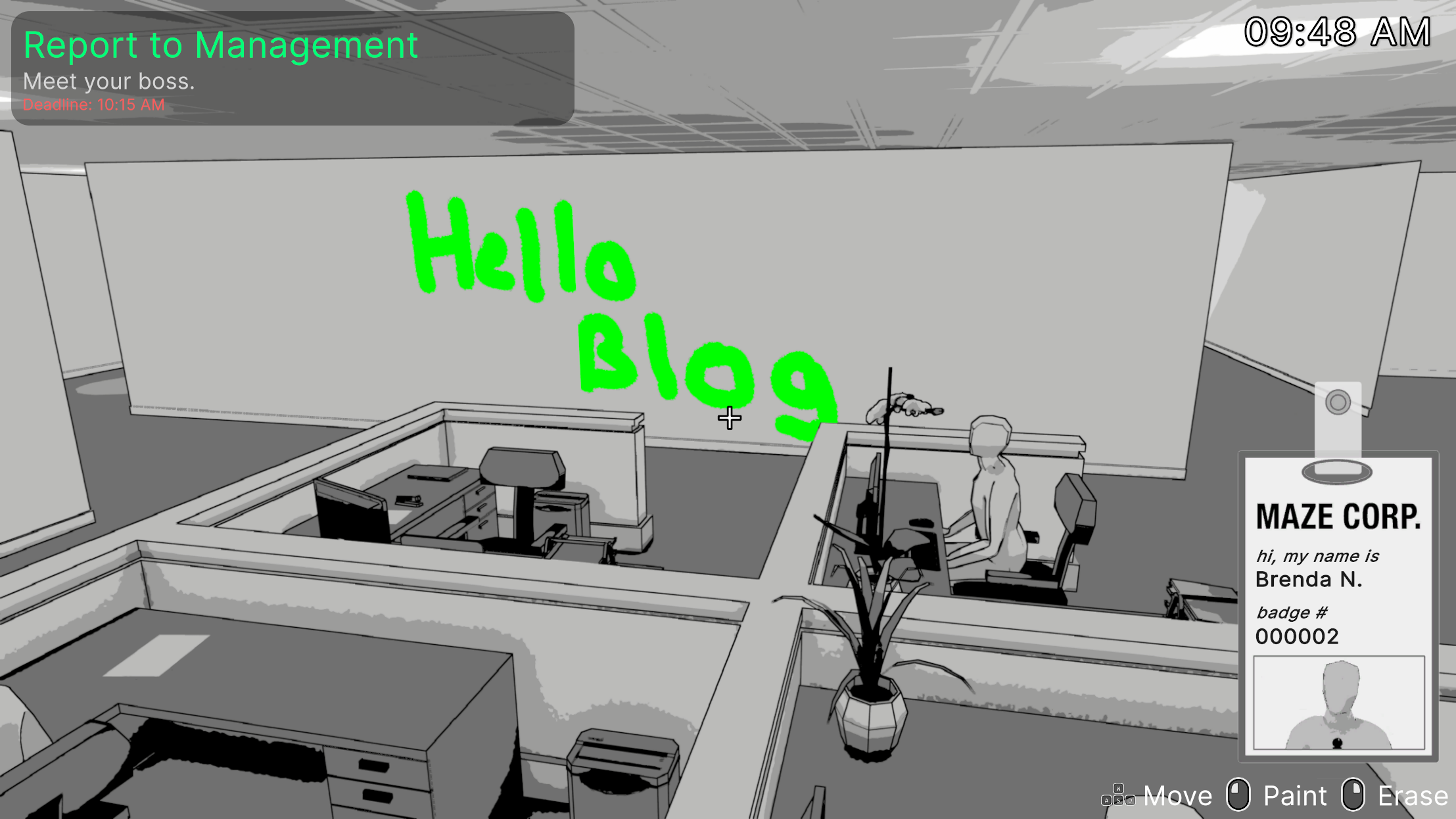
Color
But wait! Aren’t we converting the image to grayscale in the post-processing shader? Why is the paint colorful?
Good question! My post-processing shader runs after opaques (non-transparent) are drawn. I cheated a little bit and made the paint material transparent. Since all transparent materials are rendered after the post-processing pass, they’re never converted to grayscale and instead drawn on top of the posterized image. There are other areas in the game we use color and they all are done with transparent materials. There are probably more correct ways of doing this with more custom render passes but this felt like the simplest way to implement it for the game jam.
Conclusion
I hope this was an interesting read and that you learned something or got inspired to make your own effects. I’m really glad I had the opportunity to spend so much time working on aesthetics during a game jam! If you’re interested in playing the final product you can download it on itch.io or you can check out the full source code on github.